Once more some throughput tests, this time the Palo Alto Networks firewalls site-to-site IPsec VPN. Similar to my VPN speedtests for the FortiGate firewall, I set up a small lab with two PA-200 firewalls and tested the bandwidth of different IPsec phase 2 algorithms. Compared to the official data sheet information from Palo Alto that state an IPsec VPN throughput of 50 Mbps, the results are really astonishing.
Lab
My lab consists of two PA-200 firewalls with PAN-OS 7.1.1 installed. They were plugged into a simple layer 2 switch. The two notebooks were booted with Knoppix 7.6.1 and used Iperf version 2.0.5.
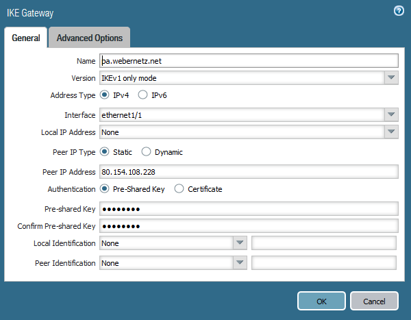
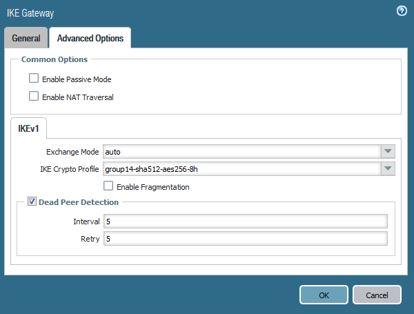
I first tested the throughput with only routing and then built the VPN. After every test I changed the phase 2 parameters. The Iperf tests ran in both directions. Here are some configuration screenshots:
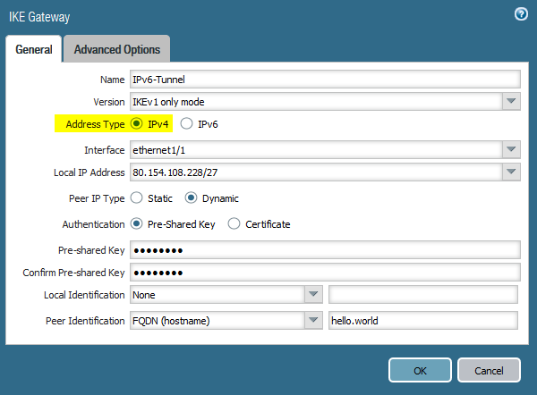
IKE Gateway
Ike Gateway Advanced
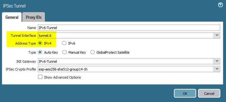
IPsec Tunnel
Traffic Log with different Zones
Of course I verified the correct IPsec algorithms after each change, such as here:
Show IPSec SA:Total8tunnels found.1ipsec sa found.
Test Results
Here are the results, each Tx/Rx in Mbps:
foobar
No VPN Tx
No VPN Rx
3des-sha1-group2 Tx
3des-sha1-group2 Rx
aes128-sha1-group5 Tx
aes128-sha1-group5 Rx
aes256-sha256-group14 Tx
aes256-sha256-group14 Rx
aes256-sha512-group20 Tx
aes256-sha512-group20 Rx
blubb
937
934
198
228
215
271
205
254
212
260
And the raw values:
Only routing: 937/934
esp-3des-sha1-group2-1h: 198/228
esp-aes128-sha1-group5-1h: 215/271
esp-aes256-sha256-group14-1h: 205/254
esp-aes256-sha512-group20-1h: 212/260
That is: All tests are around 200 Mbps. The Tx direction is always a bit slower, which might be a test failure. The AES algorithms are faster than the old 3DES cipher. This might be related to the fact that AES is made to be fast in software and in hardware.
Conclusion
Wow, these are really high values. The data sheet talks about 50 Mbps, even for the bigger PA-500 firewall. I don’t know why, but my test results are four times greater than the official notes. Ok, I can live with that. 😉
After I have done some speedtests on the FortiGate firewall I was interested in doing the same tests on a Palo Alto. That is: What are the throughput differences of IPv4 vs. IPv6, measured with and without security profiles, i.e., with and without threat prevention. It turned out that the throughput is much higher than the official information from Palo Alto. Furthermore, I was not able to test the threat prevention at all, because non of my traffic (Iperf and mere HTTP) went through the antivirus engines. I have to test this again. However, here are the measured values so far:
Laboratory & Scenarios
I had a single PA-200 with PAN-OS 7.1.1 installed. The two test notebooks ran Knoppix 7.6.1 and Iperf version 2.0.5. This time I only used the TCP test. For the HTTP tests I used an Apache2 webserver on the one side and wget on the other side. I tested the following scenarios, all of them routed through the Palo Alto:
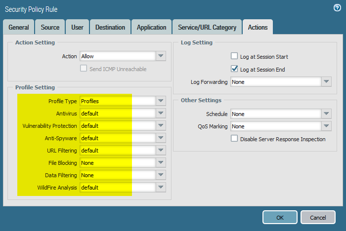
Iperf, single policy rule, NO security profiles, both directions. This was recognized as “unknown-tcp” though the application “iperf” exists. (Refer to Applipedia.)
Iperf, with security profiles, still recognized as unknown-tcp, both directions.
Iperf, with security profiles and app-override, now displayed as “iperf”, both directions.
HTTP, with security profiles, recognized as “web-browsing”, only server to client direction, but with enabled server response inspection.
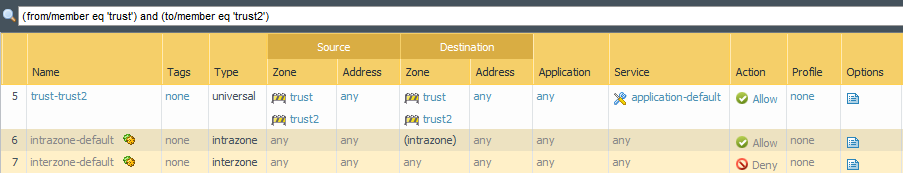
Here are a few screenshots of the policies and the traffic log:
All measured values are almost around 930 Mbps, except the Apache/wget/HTTP traffic. I suppose that this comes from other parameters such as the Apache server, the local file reading/writing, or wget. For the sake of completeness, these are the raw values, each with Tx/Rx in Mbps:
Iperf with security profiles and app override -> iperf: IPv4 = 942/936, IPv6 = 929/923
HTTP with security profiles, web-browsing, single direction: IPv4 = 774, IPv6 = 704
Conclusion
Ok, this is really strange! Palo Alto lists a firewall throughput for the PA-200 of 100 Mbps and a threat prevention throughput of 50 Mbps. My tested results are way beyond that. Much better compared to the results from the FortiGate are the “v4 vs. v6” differences. Both protocols are almost at the same speed. Concerning the security profiles: As long as the application is not recognized correctly (and only shown as unknown-tcp), the threat prevention will not work. That’s ok. Similar to the app override, refer to this PAN documentation: “An application override with a custom application will prevent the session from being processed by the App-ID engine, which is a Layer-7 inspection.” But why is the threat prevention not working for the web-browsing traffic? The throughput should dramatically decrease when the whole traffic is scanned for viruses, etc., shouldn’t it?
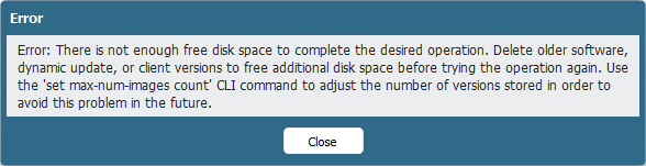
I had an error on my PA-200 with PAN-OS 7.0.5 while trying to download a new firmware version. “Error: There is not enough free disk space to complete the desired operation. […]”. Even the tips to delete older software, dynamic updates, etc., and to use the “set max-num-images count” command did not lead to a successful download. Finally, the TAC support could solve the problem via root access to the Palo Alto firewall and by manually moving data files…
This was the disk space on the firewall before the TAC support corrected it (note the 5th line with 92 % usage):
1
2
3
4
5
6
7
8
weberjoh@fd-wv-fw02>show system disk-space
Filesystem Size Used Avail Use%Mounted on
/dev/sda31.9G1.5G393M79%/
/dev/sda56.6G5.8G541M92%/opt/pancfg
/dev/sda61.9G685M1.2G38%/opt/panrepo
tmpfs1.3G116M1.2G10%/dev/shm
/dev/sda82.4G1.9G372M84%/opt/panlogs
And on my monitoring server I could see that the management config partition increased its usage a few weeks ago: The supporter now used the debug tac-login challenge and debug tac-login response commands to gain root access on my PA-200. (Interesting…) He said that the problem is due to not deleted AV- and content-packages. He then did the following steps:
He navigated to the folder in which the AV and content packages reside.
He moved the “newav” folder to another partition. Now there was enough disk space on the current partition.
Via the GUI, he upgraded the content packages. This worked and PAN-OS correctly deleted the temporary content files.
He then moved back the AV files (newav) to the original partition
and upgraded the AV packages appropriately. This worked, too, and PAN-OS correctly deleted the temporary AV files, too.
Now the usage of /dev/sda5, mounted on /opt/pancfg, was about 73 %:
1
2
3
4
5
6
7
8
weberjoh@fd-wv-fw02>exitshow system disk-spacejobs allsystem disk-space
Filesystem Size Used Avail Use%Mounted on
/dev/sda31.9G1.5G391M79%/
/dev/sda56.6G4.6G1.8G73%/opt/pancfg
/dev/sda61.9G685M1.2G38%/opt/panrepo
tmpfs1.3G116M1.2G10%/dev/shm
/dev/sda82.4G2.0G330M86%/opt/panlogs
This is the daily graph of the management config partition which shows the decrease of the space usage during the support call: After this procedure, I was able to update man PAN-OS to a newer version. Thank you. And hopefully this bug will be fixed in an upcoming version! (Bug number 94106.)
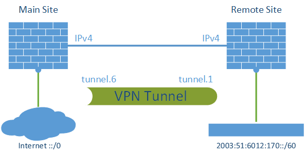
The most common transition method for IPv6 (that is: how to enable IPv6 on a network that does not have a native IPv6 connection to the Internet) is a “6in4” tunnel. Other tunneling methods such as Teredo or SixXS are found on different literatures as well. However, another method that is not often explained is to tunnel the IPv6 packets through a normal VPN connection. For example, if the main office has a native IPv6 connection to the Internet as well as VPN connections to its remote offices, it is easy to bring IPv6 subnets to these stations. Here comes an example with two Palo Alto firewalls.
I assume that there is already a VPN connection between two Palo Alto firewalls in place. If so, the steps to tunnel IPv6 through this VPN tunnel are quite easy. (Note that this is NOT a 6in4 tunnel! It is simply a forwarding of IPv6 packets through a common IPsec site-to-site VPN.)
Tunneling
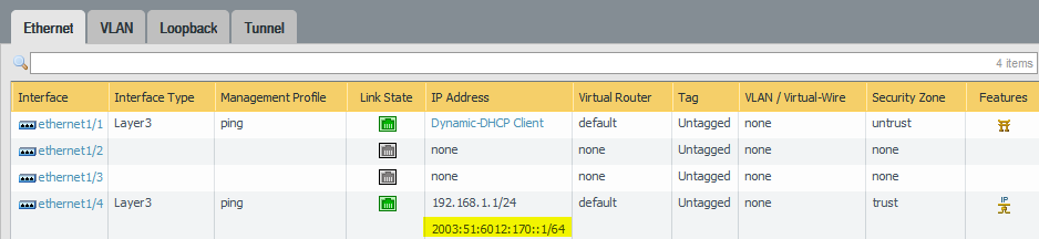
I am using two PA-200 firewalls with PAN-OS 7.1.1. One firewall has a static IPv4 address, the other one is dynamic. I am routing a /60 through the tunnel to have a maximum of 16 subnets on the remote site. This is how the lab looks like: The basic step is to enable IPv6 on the tunnel interfaces and to route the IPv6 traffic appropriately. Of course, all other interface configuration steps such as router advertisements as well as security policies must be configured, too.
Main Site
These are the configuration steps on the main site in order to route the IPv6 subnet through the tunnel. See the screenshot descriptions for more details:
Remote Site
Very similar: the remote site. Note the default IPv6 route through the tunnel:
Latency & Hop Count
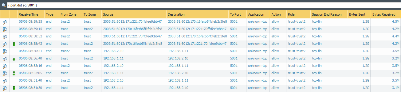
After committing everything the traffic log shows some IPv6 connections, either from trust to vpn-s2s (on the remote site), or from vpn-s2s to untrust (on the main site):
It is interesting to see the IPv6 ping times from the remote site compared to the IPv4 ping times. Since the IPv6 connections must travel through the IPv4 VPN tunnel via the Internet before reaching the real destination, the RTT should be much higher than the IPv4 times. However, everything is relative. 😉 The ping times (IPv6 and IPv4) on my main site are both around 5-8 ms in the following example:
1
2
3
4
5
6
7
8
9
10
11
12
13
14
15
16
17
18
19
20
21
22
23
24
25
26
27
28
29
C:\Users\weberj>ping-4www.insinuator.net
Ping wird ausgeführtfürwww.insinuator.net[62.159.96.203]mit32Bytes Daten:
Antwort von62.159.96.203:Bytes=32Zeit=8msTTL=57
Antwort von62.159.96.203:Bytes=32Zeit=6msTTL=57
Antwort von62.159.96.203:Bytes=32Zeit=8msTTL=57
Antwort von62.159.96.203:Bytes=32Zeit=5msTTL=57
Ping-Statistikfür62.159.96.203:
Pakete:Gesendet=4,Empfangen=4,Verloren=0
(0%Verlust),
Ca.Zeitangaben inMillisek.:
Minimum=5ms,Maximum=8ms,Mittelwert=6ms
C:\Users\weberj>
C:\Users\weberj>
C:\Users\weberj>ping-6www.insinuator.net
Ping wird ausgeführtfürwww.insinuator.net[2003:60:4010:11b0::12]mit32Bytes Daten:
Antwort von2003:60:4010:11b0::12:Zeit=5ms
Antwort von2003:60:4010:11b0::12:Zeit=5ms
Antwort von2003:60:4010:11b0::12:Zeit=5ms
Antwort von2003:60:4010:11b0::12:Zeit=5ms
Ping-Statistikfür2003:60:4010:11b0::12:
Pakete:Gesendet=4,Empfangen=4,Verloren=0
(0%Verlust),
Ca.Zeitangaben inMillisek.:
Minimum=5ms,Maximum=5ms,Mittelwert=5ms
But since my remote site is a DSL connection with a slower latency at all, the IPv6 burden is not that high, as seen here. Both connections are around 30 ms:
1
2
3
4
5
6
7
8
9
10
11
12
13
14
15
16
17
18
19
20
21
22
23
24
25
26
27
28
29
C:\Users\Johannes Weber>ping-4www.insinuator.net
Ping wird ausgeführtfürwww.insinuator.net[62.159.96.203]mit32Bytes Daten:
Antwort von62.159.96.203:Bytes=32Zeit=32msTTL=54
Antwort von62.159.96.203:Bytes=32Zeit=31msTTL=54
Antwort von62.159.96.203:Bytes=32Zeit=31msTTL=54
Antwort von62.159.96.203:Bytes=32Zeit=31msTTL=54
Ping-Statistikfür62.159.96.203:
Pakete:Gesendet=4,Empfangen=4,Verloren=0
(0%Verlust),
Ca.Zeitangaben inMillisek.:
Minimum=31ms,Maximum=32ms,Mittelwert=31ms
C:\Users\Johannes Weber>
C:\Users\Johannes Weber>
C:\Users\Johannes Weber>ping-6www.insinuator.net
Ping wird ausgeführtfürwww.insinuator.net[2003:60:4010:11b0::12]mit32Bytes Daten:
For a basic remote access VPN connection to a Palo Alto Networks firewall (called “GlobalProtect”), the built-in VPN feature from Android can be used instead of the GlobalProtect app from Palo Alto itself. If the additional features such as HIP profiling are not needed, this variant fits perfectly. I am showing a few screenshots and logs from the Android smartphone as well as from the Palo Alto to show the differences.
This post is very similar to the post about the iPhone. I am running a PA-200 with PAN-OS version 7.0.3. The phone is a Samsung Galaxy S4 Mini with Android version 4.4.2. The GlobalProtect app from Palo Alto works without any problems if a correct Portal and Gateway are already configured. In order to use the native “IPSec Xauth PSK” on Android, the “X-Auth Support” must be enabled on the GlobalProtect Gateway, such as shown here in my post about the Linux vpnc client.
GlobalProtect App vs. Native VPN
The following Android screenshots show the configuration steps for the native IPsec VPN tunnel. The “IPSec Xauth PSK” type must be chosen:
Just for a comparison: The GlobalProtect app looks like that:
Palo Alto Logs
It is interesting to see the differences in the Palo Alto logs, i.e., the GlobalProtect Previous User, System Log and Traffic Log. Here are the differences:
Policy Based Forwarding on a Palo Alto with different Virtual Routers
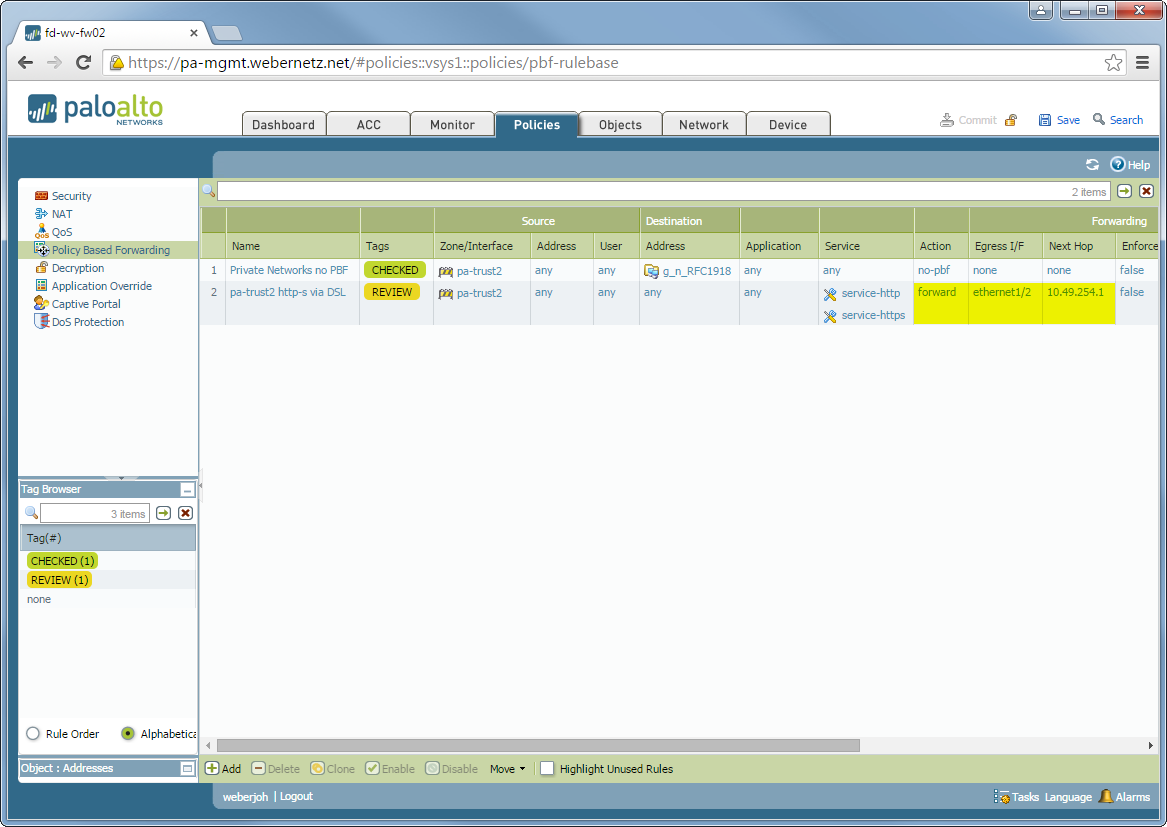
This guide is a little bit different to my other Policy Based Forwarding blog post because it uses different virtual routers for both ISP connections. This is quite common to have a distinct default route for both providers. So, in order to route certain traffic, e.g., http/https, to another ISP connection, policy based forwarding is used.
There are two documents from Palo Alto that give advises how to configure PBF.
I am using a PA-200 with PAN-OS 7.0.1. My lab is the following: (Note that, unlike Juniper ScreenOS, a zone is not tied to a virtual router. You actually can merge interfaces on different vrouters into the same zone. However, I prefer to configure an extra zone for each ISP to keep my security policies clearly separated.) These are the configuration steps. See the descriptions under the screenshots for details:
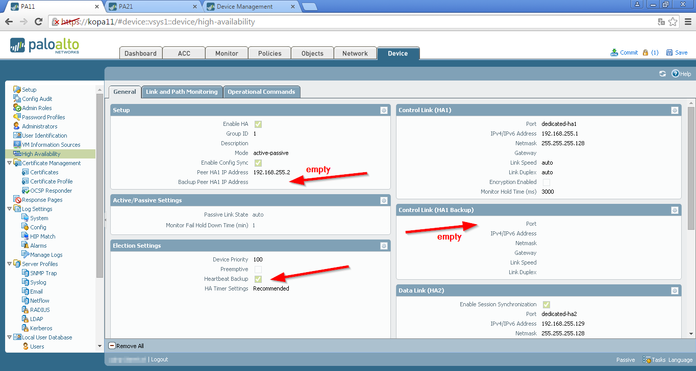
Beside the HA1 and HA2 interfaces on a Palo Alto Networks firewall, there are the HA1/HA2 Backup and Heartbeat Backup options. I was a bit confused while reading the documentation of the high availability instructions since it did not clearly specify when and where to use the dedicated management port for what kind of “backup”. Basically, it should read that there are two different ways on how to use the dedicated management for a HA Backup: the heartbeat backup OR the HA1 backup.
(The screenshots are from a PA-5050 with PAN-OS version 6.1.5 running. The official Palo Alto Networks links are here: High Availability Resources.)
I was confused because the Palo Alto documentation says about the heartbeat backup: “Uses the management ports on the HA devices to provide a backup path for heartbeat and hello messages. The management port IP address will be shared with the HA peer through the HA1 control link. No additional configuration is required.”
And for the HA1 backup, it says: “The recommended configuration for the HA control link connection is to use the dedicated HA1 link between the two devices and use the management port as the Control Link (HA Backup) interface. In this case, you do not need to enable the Heartbeat Backup option in the Elections Settings page.” –> It was not clear for me, where to use the management port and when to enable the heartbeat backup.
Solution
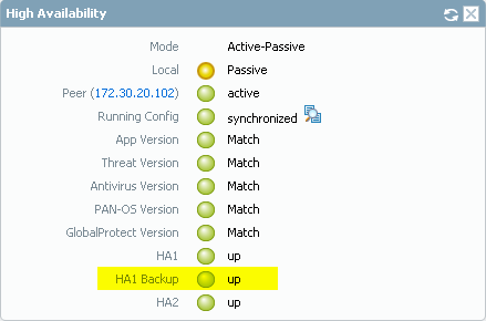
The heartbeat backup option should only be used if the management interface is not used at HA1 or HA1 backup. Otherwise, the heartbeat backup should not be used. The following two screenshots show the different options. Either the heartbeat backup is activated, or the HA1 backup link is the management interface:
In any case, the HA1 Backup bubble should be green: Note that the heartbeat backup is ONLY using heartbeat and hello messages, while the HA1/backup link does more: “Control Link: The HA1 link is used to exchange hellos, heartbeats, and HA state information, and management plane sync for routing, and User-ID information. This link is also used to synchronize configuration changes on either the active or passive device with its peer.” –> Choose the option in which the managenent interface is the real HA1 backup and not only the heartbeat backup!
Supplement
Just while searching for all that HA stuff I found a list in the admin guide for version 6.1 that exactly describes when or when not to use the “heartbeat backup” option. 😉 On page 143 it lists (among others) this cases:
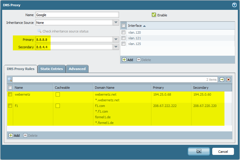
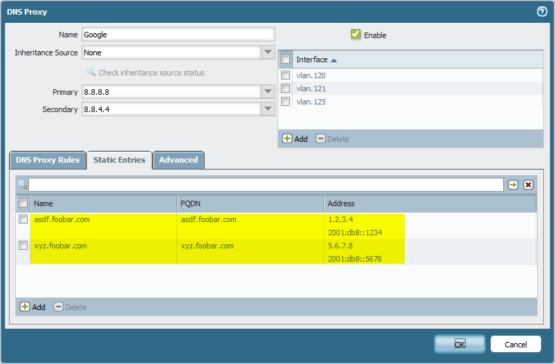
The Palo Alto firewall has a feature called DNS Proxy. Normally it is used for data plane interfaces so that clients can use the interfaces of the Palo for its recursive DNS server. Furthermore, this DNS Proxy Object can be used for the DNS services of the management plane, specified under Device -> Setup -> Services. However, there was a bug in PAN-OS that did not process the proxy rules and static entries when a DNS proxy object was used in the management plane. This bug was fixed in PAN-OS 6.0.0. I tested it in my lab with PAN-OS 6.1.0 running. Here are the successful results.
The fixed bug in version 6.0.0 was bug ID 41472: “When a DNS Proxy object was configured with static entries, hostnames assigned to the DNS Proxy were resolved as expected to the IP addresses listed on the Static Entries tab (Network > DNS Proxy) . However, when setting the DNS Proxy Object as the DNS Service on the Device > Setup > Services dialog, all DNS queries from the management interface ignored the defined static entries.”
DNS Proxy
I added a DNS proxy called “Google” with their two public DNS servers, as well as a few proxy rules to other DNS servers and static entries. This proxy object was then referenced for the management services as a “DNS Proxy Object”:
Tests
After a commit, I pinged a few hosts from the management plane. The first one should use the default DNS server, while the three following requests should use the proxy rules. The last object was the static entry in the DNS proxy.
1
2
3
4
5
6
7
8
9
10
11
12
13
14
15
16
17
18
19
20
21
22
23
24
25
26
27
28
29
30
31
32
33
34
35
36
37
weberjoh@fd-wv-fw02> ping host heise.de
PING heise.de (193.99.144.80) 56(84) bytes of data.
64 bytes from redirector.heise.de (193.99.144.80): icmp_seq=1 ttl=245 time=44.0 ms
64 bytes from redirector.heise.de (193.99.144.80): icmp_seq=2 ttl=245 time=12.5 ms
^C
--- heise.de ping statistics ---
2 packets transmitted, 2 received, 0% packet loss, time 1008ms
rtt min/avg/max/mdev = 12.514/28.279/44.044/15.765 ms
weberjoh@fd-wv-fw02> ping host webernetz.net
PING webernetz.net (80.237.133.136) 56(84) bytes of data.
64 bytes from wp367.webpack.hosteurope.de (80.237.133.136): icmp_seq=1 ttl=55 time=86.9 ms
64 bytes from wp367.webpack.hosteurope.de (80.237.133.136): icmp_seq=2 ttl=55 time=66.9 ms
^C
--- webernetz.net ping statistics ---
2 packets transmitted, 2 received, 0% packet loss, time 1004ms
rtt min/avg/max/mdev = 66.965/76.949/86.933/9.984 ms
weberjoh@fd-wv-fw02> ping host ra.webernetz.net
PING ra.webernetz.net (192.168.112.4) 56(84) bytes of data.
64 bytes from 192.168.112.4: icmp_seq=1 ttl=62 time=1.13 ms
64 bytes from 192.168.112.4: icmp_seq=2 ttl=62 time=1.20 ms
^C
--- ra.webernetz.net ping statistics ---
2 packets transmitted, 2 received, 0% packet loss, time 1008ms
rtt min/avg/max/mdev = 1.139/1.170/1.201/0.031 ms
weberjoh@fd-wv-fw02> ping host www.formel1.de
PING www.formel1.de (78.138.119.82) 56(84) bytes of data.
64 bytes from f1-lb01.formel1.de (78.138.119.82): icmp_seq=1 ttl=53 time=11.9 ms
64 bytes from f1-lb01.formel1.de (78.138.119.82): icmp_seq=2 ttl=53 time=52.4 ms
^C
--- www.formel1.de ping statistics ---
2 packets transmitted, 2 received, 0% packet loss, time 1009ms
rtt min/avg/max/mdev = 11.925/32.206/52.487/20.281 ms
weberjoh@fd-wv-fw02> ping host asdf.foobar.com
PING asdf.foobar.com (1.2.3.4) 56(84) bytes of data.
^C
--- asdf.foobar.com ping statistics ---
2 packets transmitted, 0 received, 100% packet loss, time 999ms
Since the default route of the management interface points through one of the data interfaces of the Palo Alto, I could easily do a packet capture on the Palo itself. It correctly revealed the three different DNS servers for the requests. Of course, the request to the static entry is not shown since it did not trigger a DNS request to a server.
Works as Expected
The tests showed that the function of a DNS proxy for the management services works as expected. Not only the default DNS servers, but also the proxy rules and static entries are used through the management plane. Note that the following scenarios do NOT work:
Pre PAN-OS 6.x, the DNS Proxy object used in the management services sent all requests to the primary and secondary DNS servers but NOT to the proxy rules. The static entries were not used, too.
It is not possible to set a “DNS Server” in the management services to the IP address of a data interface of the Palo Alto itself. This won’t work since the Palo uses some kind of internal path when sending packets to an own data interface. This means, if a DNS Proxy object should be used, it must be selected as a “DNS Proxy Object” and not as an entry of “DNS Servers”.
When working with Cisco devices anyone knows that the output of a “show running-config” on one device can be used to completely configure a new device. On a Palo Alto Networks firewall, this is not that obvious. There are several commands that must be used to achieve the same. However, I tested this procedure a few times and it did NOT work. 🙁 So, the short version is: If you want to replace a Palo Alto firewall, move your configuration files (xml) through the GUI or tftp/scp. But do not use the mere CLI.
The most common way to save a Palo Alto config is via the GUI at Device -> Setup -> Operations -> Export xyz. And even on the CLI, the running-config can be transferred via scp or tftp, such as scp export configuration from running-config.xml to username@host:path . This configuration file can be loaded into a new device, again, via the GUI (Import) or the CLI ( scp import configuration from username@host:path ).
Save
However, to save the complete configuration in the “set” format, the following CLI commands must be used. The first one is used to output the configuration in single “set” lines (instead of XML blocks), and the second one switches the output to not stop after a few lines on the terminal. To capture long lines without a “carriage return”, the terminal width should be adjusted to the maximum of 500. Then, the “configure” command enters the configuration mode, while the “show” command displays the whole running configuration.
1
2
3
4
5
> set cli config-output-format set
> set cli pager off
> set cli terminal width 500
> configure
# show
And Load
To load the config into a new device, a few commands must be used before. At first, the terminal width should be adjusted again. Furthermore, the scripting-mode must be enabled in order to send a bulk of CLI commands without an error. The reason for that is, that several objects are referenced in the configuration before they are added to the device. E.g., the set commands for the “security rules” are before the set commands for the “application groups”. That is, an application group is used by a security rule before it is added to the config. 🙁 Finally, the whole bunch of set commands from above can be pasted into the CLI session.
1
2
3
4
> set cli terminal width 500
> set cli scripting-mode on
> configure
# set ...
Errors, Errors, Errors
I wanted to load a complete configuration from a firewall to another. (Both firewalls were of the same type, OS version (6.0.x) and license.) I used the console port on the device. But even with the aforementioned commands that should make this procedure possible, I got only errors, such as: “Invalid syntax.” or “Unknown command: …”. Furthermore, the terminal session looked like a complete chaos:
1
2
3
4
5
6
7
8
9
10
11
12
admin@PA-5050#
Server error : -> from 'trustL3' is not an allowed keyword
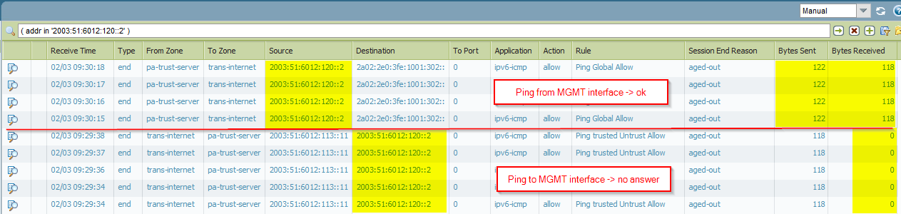
A few month ago I found a small bug in PANOS, the operating system from Palo Alto Networks. It is related to an IPv6 enabled management interface. The MGT address was not reachable when the firewall operates in layer 2 mode, that is, had layer 2 interfaces along with VLANs. Luckily, this bug is fixed with the new software version 6.1.2 which was released this week (bug ID 67719). Following are a few listings that show the incomplete handling of the IPv6 neighbor cache of the MGT interface in the old version (pre 6.1.2).
I was using the layer 2 mode for some switch tests about STP. During these tests I noticed that I was not able to connect to the MGT interface via IPv6 anymore. The Palo Alto in my lab has a VLAN interface (vlan.120) and the corresponding VLAN on a layer 2 subinterface. The management port is plugged into a switch in the same VLAN. The IPv6 address on the MGT interface is 2003:51:6012:120::2/64 .
Bug
For example, when trying to ping or to ssh to the MGT interface from another machine …
However, I was able to ping from that MGT interface IPv6 address. Interestingly, the neighbor cache revealed the ::2 address, but only with the status “PROBE” and only for a very few seconds:
The traffic log on the Palo Alto shows that incoming connections did not succeed, while outgoing connections did:
Fixed in 6.1.2
with bug ID 67719: “The management interface was not receiving IPv6 connections for traffic from the dataplane when the firewall was in Layer 2 mode. An update was made to the MAC address learning process so that the Management interface receives IPv6 traffic from the dataplane when the firewall is in Layer 2 mode.” Now I can ping to the IPv6 MGT address:
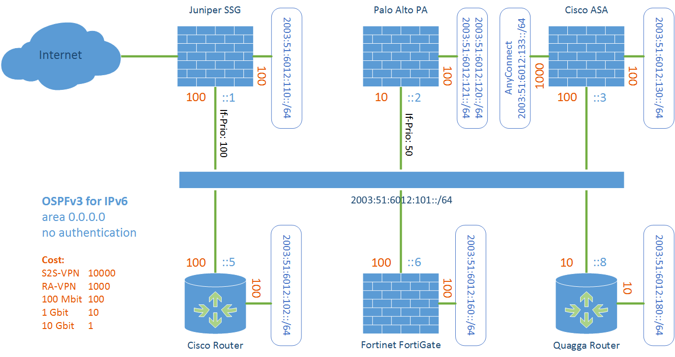
Similar to my test lab for OSPFv2, I am testing OSPFv3 for IPv6 with the following devices: Cisco ASA, Cisco Router, Fortinet FortiGate, Juniper SSG, Palo Alto, and Quagga Router. I am showing my lab network diagram and the configuration commands/screenshots for all devices. Furthermore, I am listing some basic troubleshooting commands. In the last section, I provide a Tcpdump/Wireshark capture of an initial OSPFv3 run. I am not going into deep details of OSPFv3 at all. But this lab should give basic hints/examples for configuring OSPFv3 for all of the listed devices.
Lab
This is my test lab. All devices are directly connected via a layer 2 switch:
General Information
Everything takes place in area 0.0.0.0 (backbone area)
Juniper SSG should be the DR: interface priority set to 100.
Palo Alto should be the BDR: interface priority set to 50.
Router-ID is always set manually according to my IPv4 sheme: 172.16.1.x, where x = the interface-ID from the IPv6 addresses (from ::1 to ::6).
Cost for the interfaces as seen in the figure.
Passive-interface on all user/access interfaces.
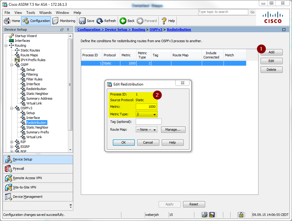
Redistribution of the remote access VPN clients on the Cisco ASA (AnyConnect).
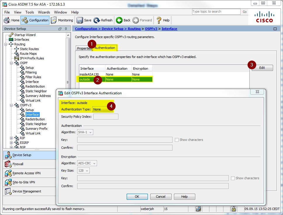
No authentication is used .
The following devices are in alphabetic order. Beneath each screenshot is a detailed description of the the configuration that is shown. During the tests, a single Cisco AnyConnect client was connected and therefore redistributed with a /128 IPv6 address prefix. The Quagga router was added to this lab after most of the listings were saved. That is: The Quagga router (172.16.1.8) is not shown on any other firewalls/routers.
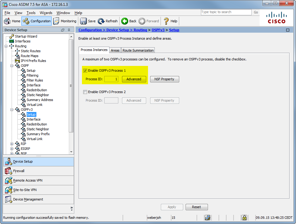
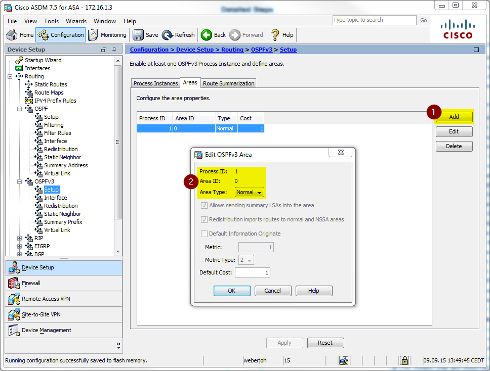
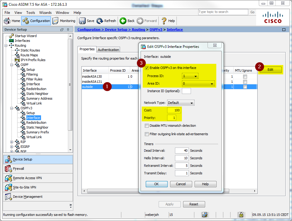
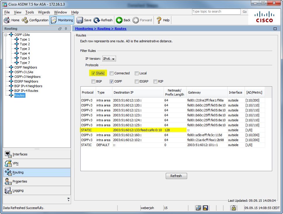
Cisco ASA
The Cisco ASA 5505 is running version 9.2(4). Following are the configuration and monitoring screenshots:
This are the relevant CLI commands for the OSPFv3 config:
1
2
3
4
5
6
7
8
9
10
11
12
13
14
15
interfaceVlan130
ipv6 address2003:51:6012:130::1/64
ipv6 address autoconfig
ipv6 enable
ipv6 ospf cost100
ipv6 ospf1area0
ipv6 ospf encryption null
!
ipv6 router ospf1
router-id172.16.1.3
passive-interfaceinsideASA130
passive-interfaceinsideASA131
log-adjacency-changes
redistribute static metric1000
!
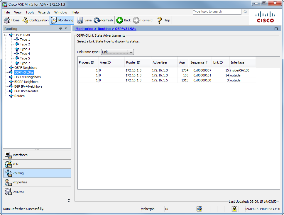
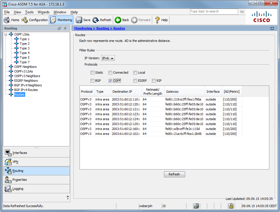
While this CLI commands can be used to show the OPSFv3 runtime values:
Click To Expand Code
Cisco Router
I am running a Cisco 2811 router with version 15.1(4)M9. The configuration commands are the following: (Just for fun I set the OSPF process to “17”.)
1
2
3
4
5
6
7
8
9
10
11
12
13
14
15
16
interfaceFastEthernet0/0
ipv6 address2003:51:6012:101::5/64
ipv6 enable
ipv6 nd ra suppress
ipv6 ospf17area0.0.0.0
!
interfaceFastEthernet0/1
ipv6 address2003:61:6012:102::1/64
ipv6 enable
ipv6 ospf17area0.0.0.0
!
ipv6 router ospf17
router-id172.16.1.5
auto-cost reference-bandwidth10000
passive-interfacedefault
no passive-interfaceFastEthernet0/0
And the show commands:
1
2
3
4
5
6
7
8
9
10
11
12
13
14
15
16
17
18
19
20
21
22
23
24
25
26
27
28
29
30
31
32
33
34
35
36
37
38
39
40
41
42
43
44
45
46
47
48
49
50
51
52
53
54
55
56
57
58
59
60
61
62
63
64
65
66
67
68
69
70
71
72
73
74
75
76
77
78
79
80
81
82
83
84
85
86
87
88
89
90
91
92
93
94
95
96
97
98
99
100
101
102
103
104
105
106
107
108
109
110
111
112
113
114
115
116
117
118
119
120
121
122
123
124
125
126
127
128
129
130
131
132
133
134
135
136
137
138
139
140
141
142
fd-wv-ro03#show ipv6 ospf
Routing Process"ospfv3 17"with ID172.16.1.5
Event-log enabled,Maximum number of events:1000,Mode:cyclic
Initial SPF schedule delay5000msecs
Minimum hold timebetween two consecutive SPFs10000msecs
Maximum waittimebetween two consecutive SPFs10000msecs
Minimum LSA interval5secs
Minimum LSA arrival1000msecs
LSA group pacing timer240secs
Interfaceflood pacing timer33msecs
Retransmission pacing timer66msecs
Number of external LSA1.Checksum Sum0x004DAC
Number of areas inthisrouter is1.1normal0stub0nssa
Graceful restart helper support enabled
Reference bandwidth unit is10000mbps
Area BACKBONE(0.0.0.0)
Number of interfaces inthisarea is2
SPF algorithm executed23times
Number of LSA19.Checksum Sum0x098B75
Number of DCbitless LSA6
Number of indication LSA0
Number of DoNotAge LSA0
Flood list length0
fd-wv-ro03#
fd-wv-ro03#
fd-wv-ro03#show ipv6 ospf neighbor
Neighbor IDPri State Dead TimeInterfaceIDInterface
Pro Teknologi dibuat pada 22 Februari 2017. Blog ini adalah harapan saya agar dapat membagi manfaat kepada orang lain,berupa tips-tips Seputar Blog,Internet,Komputer,dan Info-Info Menarik lainnya.


0 Response to "Palo Alto Information"
Post a Comment